


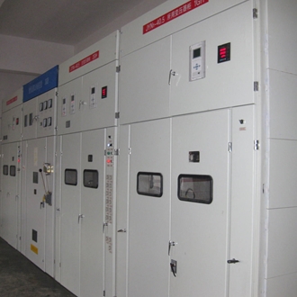
Jyn1-40.5 interval removable ac metal enclosed switchgear
Air insulated switchgear
Scope of application :
It is suitable for indoor complete set of three-phase ac 50Hz single bus and single bus breaking system. product details
JYN1 40.5 move open between ac metal-enclosed switchgear series three-phase ac 50 hz single busbar and busbar breaking indoor complete sets of equipment of the system,and as small and medium-sized power plants,substations,and accepted by the industrial and mining enterprises,power distribution and allocation of electricity used indoor switchgear,may also be starting,stop the motor,to the capacitor,frequent operation equipment such as electric furnace transformer control equipment.
This product complies with GB3906"3~35kV ac metal closed switch equipment",GB/T11022"high voltage switch equipment and control equipment standard sharing technical requirements",IEC60298"rated voltage above 1KV 52KV and below ac metal closed switch equipment and control equipment",IEC60694"high voltage switch equipment and control equipment sharing terms"and other standard requirements.
Ii.Conditions of use
1.Upper limit of ambient air temperature:+40℃,lower limit:-10℃,daily average temperature not exceeding 35℃;
2.The altitude is no more than 1000 meters;
3.The daily average relative environmental humidity is no more than 95%,and the monthly average is no more than 90%;
4,the earthquake intensity does not exceed 8;
5.The daily average steam pressure shall not exceed 2.2kpa,and the monthly average shall not exceed 1.8kpa;
6.Places free from fire,explosion,serious pollution,chemical corrosion and violent vibration.
Note:users can negotiate with us if the above conditions are exceeded.
Iii.Model meaning
4.Structural features
Jyn1-40.5 spaced-open ac metal enclosed switch equipment belongs to spaced-type structure,which is composed of cabinet body formed by bending and welding of section steel and steel plate and handcart.Handcart according to its USES can be divided into the circuit breaker handcart,lightning arrester handcart,isolate the handcart,"Y"shaped connection handcart,"V voltage transformer connection handcart handcart,single phase voltage transformer and voltage transformer station transformer handcart seven,including the circuit breaker handcart ZN85-40.5 vacuum circuit breaker handcart,ZN23-40.5 vacuum circuit breaker handcart and SF6 circuit breaker handcart.
The switch equipment has the function of"five guard"interlock,which can prevent the handcart of circuit breaker from being pushed and pulled by load,the circuit breaker from being opened by mistake,the circuit breaker from being closed when the earth switch is in the closed position,and the earth switch from being closed by mistake when the earth switch is charged.
It can be equipped with zn85-40.5 fully insulated vacuum circuit breaker with excellent performance,screw nut drive,overrunning clutch,which has excellent arc extinguishing performance,easy operation,maintenance-free and other outstanding advantages.
The insulation level of switch equipment can be improved by selecting current transformer,voltage transformer,prop insulator,SMC insulation separator and contact box with large creeping distance and good insulation performance.
Dry type transformer can be used,which has the advantages of oil free,flame retardant,economical operation and maintenance free.
The switchgear is divided into several functional units by purpose,which are described as follows:
A.The enclosure of switchgear is provided with lP2X protection class,which can prevent objects with diameter greater than 12mm from approaching the live part and touching the moving part of the cabinet.The door of high voltage interval USES copper braid wire besides metal hinge to make the door connect with cabinet body.Inspection Windows are provided on the front and back shells of the switchgear to observe the operation of the equipment inside the switchgear.
B.handcart chamber
Two doors open at the bottom of the front of the switchgear,which is the handcart room.There is an insulation partition between the room and the upper and lower contact room,and a metal partition between the main bus line of the top of the cabinet.The bottom of the handcart room is provided with handcart track,and the handcart grounding device is in the center of the two tracks.A heater specially designed to prevent condensation is also located on the right side of the chamber.
C.Main busbar and upper isolation contact room
The main busbar and upper isolation contact room are located on the upper part of the switchgear.The main bus lines are arranged in a triangular arrangement on the upside-down strut insulator.Next to the main bus line is the upper isolation contact seat,which can be a current transformer with a contact,a prop insulator or a wall bushing with a contact,depending on the main junction scheme.
D.Lower isolation of contact room
The lower isolation contact chamber is located at the lower part of the upper isolation contact chamber,and there is a partition between the two.Besides the current transformer or prop insulator contact seat,the ground switch or contact bus is also located in the chamber.
E.Insulation partition and insulated valve
Between the handcart room of switchgear and the isolation contact room and the cable room,a partition made of insulation material SM(:insulation valve is installed on it.The baffle board and insulating valve have lP2X protection grade.
F.Ground switch
Grounding switch as a variable element can be selected according to the needs of the project.When the feed-out loop needs to be repaired,the circuit breaker will retreat to the isolation position and close the grounding switch to ensure safety.
G.Live display device
The live display device is a variable element,which can directly reflect the live condition of the high-voltage feed line when the switch equipment is not equipped with voltage transformer.So that the ground switch before closing can determine whether the feed line is live.
H.Grounded conductor
A copper ground conductor traversing the entire width of the switchgear is installed below and behind the switchgear.The connection between the two machines can be made by the manufacturer and installed with the connection head in the equipment.
I.Installation of auxiliary circuit equipment
An instrument door and a relay room with swing door structure are arranged on the front part of the switchgear.On both sides of the room,there are small bus-crossing holes and splints for fixing control cables.On the left side,there is a small bus-terminal group.The meter door and relay room are separated from the high voltage interval by the baffles.
J.terminal room
The terminal room is located on the right side of the front of the switchgear,and the auxiliary circuit terminal group is installed in the center of the room.The upper part is the light inside the cabinet and its switch;M1 2 grounding bolt is provided below for auxiliary circuit grounding:cable clamp bracket is provided on the right side for users to fix control cable.
K.secondary plug(socket)
The connection line between the handcart and the switchgear is realized through the plug mounted on the handcart and the socket mounted on the switchgear.When the handcart is pushed to the"test position",plug it in.When the handcart exits the"test position";The plug should be unplugged.
L.small bus
The switchgear is equipped with 15 terminal groups of small bus,and the small bus is configured by the user according to the provisions of the allocation of wire.
M.condensation controller
In the high humidity area or the temperature has the big change occasion,when the switch equipment exits the operation,has the possibility to produce the condensation.Therefore,a condensation controller is installed in the switchgear to raise the temperature so that the water vapor in the air cannot condense.
N.Auxiliary loop control cable channel
The switchgear auxiliary circuit controls the cable channel(acting as secondary cable channel)located above the relay room,and the control cable is introduced from the cable channel on the left or right side of the switchgear array.
Access through the lower side of the left door of the switchgear or the lower side of the terminal room.This channel runs through each switchgear.
O.Interior lighting
Switchgear handcart room is equipped with a 22V and 100W light,the light and switch are installed above the terminal room,the operation of the light switch or bulb replacement must open the door of the terminal room to carry out.
Technical parameters
Instructions for ordering
1.Main circuit scheme diagram or main circuit system diagram;
2.Control circuit electrical schematic diagram,terminal arrangement diagram;
3.Switchgear layout plan;
4.Color of cabinet(according to company standard if not required);
5.List of components inside the cabinet(including name,specification,model and quantity of components);
6.List of necessary spare parts;
7.If you have any special requirements,please provide details.


 Focus on wechat